Sunday 31 May 2015

DiddyBorg with joystick control

The Diddyborg is a great chunky Raspberry Pi robot and feels just right for arcade-style Joystick control.


I had a Zippyy ball handle joystick knocking around so decided to use another Raspberry Pi as a controller/relay. Each axis of the joystick closes a simple mechanical switch when the handle is moved in that direction, and this is detected using the GPIO pins.


All communications between the two Pis (the A+ in the Diddyborg and the B+ controller) are via wifi.

I used a Slice of Pi board for the connections between the GPIO pins on the controlling Pi and the Joystick. I also had plenty of space to add a bi-colour LED which I use to indicate when motion commands are actively being transmitted to the diddyborg.


The code that runs on the controlling Pi and the DiddyBorg Pi is available on GitHub.


Handheld Humidity Measuring with Astro-Pi

The main theme of our winning entry for the Astro-Pi completion was detecting the 'sweaty astronaut' using the HAT's humidity sensor.


To test how this might work,  and to build a simple demonstration for the CodeClub team,  we wrote some Python to use the Astro-Pi's awesome LED matrix to display the latest readings from the humidity sensor.

Adding a battery pack turns this into a useful hand-held humidity sensor (you could easily use it as a thermometer instead with a minor code change).

The code changes the colour of the displayed numbers based on the previous reading. If the humidity has increased then the digits are green, if it has decreased, they're red, and (you guessed it) orange if there has been no change.


Of course the screen only displays two digits so when it gets really hot and steamy...


The code also logs the humidity out to a file, so you can plot humidity against time. Here is 24 hours in our house. The big spike near the start was due to another 'breath test'.


The graph above came from data that was saved every time the display was updated - every half a second - which resulted in a lot of rows! I've now modified the code so that it only writes a result to file once every 30 seconds (the display continues to update every 0.5 seconds).  Much more manageable.

Here is the code:

from astro_pi import AstroPi
import time
import logging
from datetime import datetime

ap = AstroPi()

r = [255, 0, 0]
e = [0, 0, 0]

space = [
e,e,e,e,e,e,e,e,
e,e,e,e,e,e,e,e,
]

tmstmp = time.strftime("%Y%m%d-%H%M%S")

logging.basicConfig(format='%(asctime)s %(message)s',filename='humidity'+str(tmstmp)
+'.log',level=logging.DEBUG)

def numToMatrix(num):

# define 1x8 columns that make  single digits when combined

num_1_2 = [e,e,r,e,e,e,r,e]
num_1_1 = [e,r,r,r,r,r,r,e]
num_1_0 = [e,e,e,e,e,e,r,e]

num_2_2 = [e,r,e,e,e,r,r,e]
num_2_1 = [e,r,e,e,r,e,r,e]
num_2_0 = [e,r,r,r,e,e,r,e]

num_3_2 = [e,r,e,e,r,e,r,e]
num_3_1 = [e,r,e,e,r,e,r,e]
num_3_0 = [e,r,r,r,r,r,r,e]

num_4_2 = [e,r,r,r,r,e,e,e]
num_4_1 = [e,e,e,e,r,e,e,e]
num_4_0 = [e,r,r,r,r,r,r,e]

num_5_2 = [e,r,r,r,r,e,r,e]
num_5_1 = [e,r,e,e,r,e,r,e]
num_5_0 = [e,r,e,e,r,r,e,e]

num_6_2 = [e,r,r,r,r,r,r,e]
num_6_1 = [e,r,e,e,r,e,r,e]
num_6_0 = [e,r,e,e,r,r,r,e]

num_7_2 = [e,r,e,e,e,e,e,e]
num_7_1 = [e,r,e,e,e,e,e,e]
num_7_0 = [e,r,r,r,r,r,r,e]

num_8_2 = [e,r,r,r,r,r,r,e]
num_8_1 = [e,r,e,e,r,e,r,e]
num_8_0 = [e,r,r,r,r,r,r,e]

num_9_2 = [e,r,r,r,r,e,r,e]
num_9_1 = [e,r,e,e,r,e,r,e]
num_9_0 = [e,r,r,r,r,r,r,e]

num_0_2 = [e,r,r,r,r,r,r,e]
num_0_1 = [e,r,e,e,e,e,r,e]
num_0_0 = [e,r,r,r,r,r,r,e]

# combine columns to make digits

sing_0 = num_0_0 + num_0_1 + num_0_2
sing_1 = num_1_0 + num_1_1 + num_1_2
sing_2 = num_2_0 + num_2_1 + num_2_2
sing_3 = num_3_0 + num_3_1 + num_3_2
sing_4 = num_4_0 + num_4_1 + num_4_2
sing_5 = num_5_0 + num_5_1 + num_5_2
sing_6 = num_6_0 + num_6_1 + num_6_2
sing_7 = num_7_0 + num_7_1 + num_7_2
sing_8 = num_8_0 + num_8_1 + num_8_2
sing_9 = num_9_0 + num_9_1 + num_9_2

# map digits onto appropriate strings
if num == '1':
return sing_1
if num == '2':
return sing_2
if num == '3':
return sing_3
if num == '4':
return sing_4
if num == '5':
return sing_5
if num == '6':
return sing_6
if num == '7':
return sing_7
if num == '8':
return sing_8
if num == '9':
return sing_9
if num == '0':
return sing_0

# set previous humidity value to zero

hum_prev = 0
sec_count = 0

# Main program loop

while True:

# Get humidity from astro-pi

hum_f = ap.get_humidity()
hum_int = int(hum_f)

# test to see if value is higher or lower than previous, and then set led colour appropriately 

if sec_count == 60: # only write data every 30 seconds
logging.info(hum_f)
sec_count = 0
if hum_int > hum_prev:
r = [0,255,0] # green if higher
elif hum_int == hum_prev:
r = [255,127,0] # orange if the same
else:
r = [255,0,0] # red if lower

hum_prev = hum_int
hum =  str(hum_int) # convert reading to string

image = numToMatrix(hum[1]) + space + numToMatrix(hum[0]) # build image from two digits plus spacer
ap.set_pixels(image)

time.sleep(0.5)
sec_count+=1

Friday 29 May 2015

Raspberry Pi kite mapper - Test Flight 3

We had another quick test flight of the kite-mapping rig today.


I'd drilled the balsa picavet so the A+ Pi case actually screws onto it now,  rather than being held in place by elastic bands or cable ties.


I'm glad I did, as this flight certainly tested the robustness of the whole assembly, as can be seen by the altitude readings recorded by the Pi.
After roaring into the skies, and collecting a few excellent images, the wind suddenly dropped and so did the Pi.  I managed to keep the kite in the air for a short time before a second plummet ended this test flight rather more abruptly than I'd hoped.


Fortunately,  I always attach the picavet a few metres below the kite so that (in theory) it will touch down while the kite is still aloft and providing some lift as opposed to crashing directly into the ground. This worked well today and the Pi was also lucky that it ended up in a soft patch of tall nettles. My legs were not so lucky - 8 hours later and they're are still tingling from the stings. I knew I shouldn't have worn shorts....


Here is the touchdown site  from the Pi's perspective:


Nevertheless, despite the short duration of the flight, I still managed to capture a few good images, enough to add some tiles to a map of Bedfont Lakes Country Park:


I like that you can see all the changes to the playground area since the Google Maps image was taken.


The Pi seems no worse for wear and is still working fine, so I suppose you could say this was a successful test flight.Nevertheless, I think a sturdier, surrounding case should be a priority!

Friday 15 May 2015

Kite-mapping with Raspberry Pi

Here is our Raspberry Pi Kite-mapping rig. It uses an A+ with a Xtrinsic Sensor  and ProtoCam board.


Some shots of it in action:
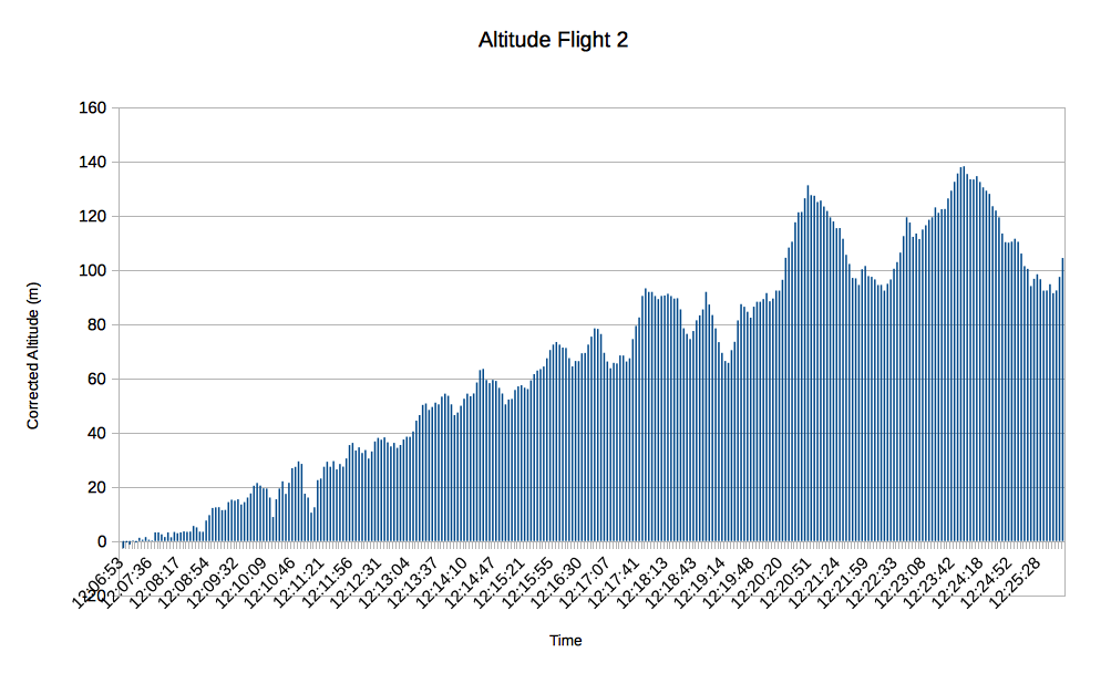


And here is the imagery produced during the second test flight over Bushy Park.

Backstory

One of the most interesting and fun and activities at last year's EMF14 festival was the kite-mapping workshops. I'd never really heard of this before but it is a simple and elegant idea: suspend a camera from a kite using a picavet, fly it and get yourself some cheap aerial photography.

Thanks to the awesome 'paying attention' skills of my son, we were able to win the workshop competition and take home a pair of kite kits and so we were well set up to try kite-mapping ourselves.

Reflecting the simplicity of the idea, most kite-mappers seem to use cheap, second hand cameras from eBay. As long as it has a continuous shoot mode and you can wedge a piece of cardboard under the shutter button, you're good to go.

However, even a second-hand camera could set you back £30 or so - comparable to the cost of a Raspberry Pi A+ and camera. I'd been thinking about a Pi-based kite-mapper over the winter and when I saw that AverageManVsRaspberryPi had released a new version of the excellent ProtoCam board for the A/B+, I decided to see what we could put together

Of course we could have just flown the Pi & camera and used the built-in functions to capture images. But I wanted to add some extra functionality. One of the problems with using a regular compact camera in continuous shoot mode is that if it is quite gusty, you can often end up with loads of 'wasted' shots as the camera swings about and isn't pointing straight down. Also, we always want to know how high the kite has gone and trying to estimate based on how much string has been unwound is really difficult and hugely inaccurate.

At first I experimented with separate MPL3115A2 and Minimu9 ICs, but then I found the Xtrinsic Sensor board from Freescale which has the altimeter, accelerometer plus a magnetometer all on a single board. There is also a useful API with some great Python sample code already available.
The fact that it comes with a header so that it can plug straight on to the GPIO pins made initial prototyping really quick.


Once we'd got some basic code running, we were then able to de-solder the header connector from the Xtrinsic and then solder the board  to the ProtoCam board using the pins designed to interface with the Freescale FRDM-KL25 platform. For added convenience we added a button to start/stop the photography and a bi-colour LED to indicate status.

First flights

Test flight one was just around the corner at the Rugby club.  It was cloudy and blustery and this was really just a test to see if the Pi rig would survive the physical conditions of flight. 


Apart from the fact that everything worked perfectly, there was one important lesson: make sure any loose cables are not impeding the lens! It was also clear that there was more that could be done in terms of selecting PiCamera settings. 

We also practiced gently bringing the Pi rig down to Earth (the helmet was because we cycled there, not for any health & safety concerns!). 

All the data recording worked as planned. Finally we could see how high the kite had gone: 120m is not bad! In theory you could use this data to automatically select the correct zoom level when adding the images to the maps using MapKnitter
Having performed some tests with various PiCamera settings, the next flight was intended to see how these worked in practice.  The wind was less constant and prone to dropping almost completely at times, as can be seen by the altitude data we recorded.  


Using the maximum resolution and making use of the image stabilisation option really helped produce some detailed, clear photographs.


We also managed to implement the safe-landing protocol successfully again:


Technical details

The pin connections between Pi and Xtrinsic board (see data-sheet for pin numbering and location) are as follows:

Pi (board / GPIO) Xtrinsic board pins
22 / GPIO25
12 / GPIO28
15 / GPIO22
13 / GPIO27
11 / GPIO11
18 / GPIO24
14 / GND
-
3 / SDA1
5 / SCL1
8 / TXD0
10 /RXD0
CN1-1
CN1-2
CN1-3
CN1-4
CN1-5
CN1-6
CN1-7
CN1-8
CN1-9
CN1-10
CN4-1
CN4-2


In terms of weight, the Pi system is slightly lighter with a compact camera. the held-together-with-duct-tape Canon Powershot I'd been using is 176g and the combined Pi and power pack comes in at 172g (the picavet and harness add an addition 60g).

The Python code and other resources are available from github.

The kite is a 9 ft wide by 4.6 ft tall delta.

Future developments:

  1. Build a more protective case for the rig. Some foamy padding around the Pi would be nice and almost certainly prolong the life of the equipment!
  2. Look at using the individual ICs directly onto the ProtoCam board. 
  3. Calibrate the magnetometer so that each picture is logged with the orientation of the camera as well as the altitude. This will help with knowing how to rotate each picture when using MapKnitter
  4. Add some automation to post-flight image processing and mapknitting.
  5. Add some additional buttons to the Pi to initiate a graceful shutdown and select various PiCamera settings (e.g. exposure, lighting type).