I've been looking for a home IoT project to setup with Amazon Alexa and my Raspberry Pi powered Christmas Tree seemed like an obvious choice.
Here's how it works:
There are 5 sets of cheapo xmas LEDs connected directly to GPIO pins on the Pi. I then use Python and GPIOZero to turn them on and off, do a bit of PWM and run some fancy sequences. I've then integrated this code into a simple Python Flask app that essentially provides a web-interface to activate the LEDs.
The Pi is also running this awesome Home Automation Bridge code from BWS Systems. This emulates the Philips Hue light system and can be easily configured to send web requests to other devices, in this case my Flask app.
Finally, Alexa discovers the HAB and merrily passes requests to it based on your voice commands.
All this runs fine on an old 512MB Raspberry Pi model B.
Step-by-step
1) Get and SD card with the latest version of Raspbian. Boot it and connect to your wifi
2) Find the if address of your Pi
pi@raspberrypi:~ $ ifconfig wlan0
wlan0 Link encap:Ethernet HWaddr 00:c1:41:39:0c:3e
5) Point a browser at the IP of your Pi (from step 2). You should be able to connect to the HAB - click on the Bridge Control tab and you should see a screen like this:
6) Clone my github with the Flask app. There are two versions of the code available: one is setup to use 5 sets of LEDs while the other is a cut down version with just a single LED string configured, connected to GPIO 14 and ground. I'm assuming you've just got one LED (or a string of LEDs) from now on.
7) Run the app:
pi@raspberrypi:~/gp0web $ python singleLED.py
* Running on http://0.0.0.0:5000/
* Restarting with reloader
8) Now we can configure our HAB. Click on the 'Manual Add' tab and fill-in the fields as shown below. The 'Unique ID' field will self-populate once you save your settings so don't worry about that.
Don't forget to change the IP address based on your setup.
9) Now save the settings and then test them. Click on the Bridge Devices tab and try to turn your LEDs on/off using the Test buttons.
If you encounter problems, check you've typed the URLs correctly and see if the Flak app is showing any errors.
10) If all is working, the final configuration step is to ask Alexa to 'discover devices'. It should respond that it found one (unless you already have other devices on your network).
11) Now you should be able to ask Alexa to "turn on tree" (or whatever name you gave to your device in step 8).
I was really excited to try out Android Things on the Raspberry Pi, especaiily with the sweet looking Pimoroni RainbowHAT, but found getting everything up and running initially a bit fiddly. Here are my notes on how it all works. I used a Mac as my developer box but I assume things will be fairly similar if you're using Windows.
1. First of all,
download
the Android Studio and install it. On a mac this just means
dragging the app into the Applications folder.
2. Now run it.
You'll be asked if you want to import anything – you probably
don't. The only other optional
configuration is to select a colour theme. I chose Dracula!
3. Now we'll be able
to connect to our Pi. Boot it from the Android SD card and wait for
the Android Things splash screen to appear. It will show you the IP
address being used by the Pi – make sure you connect it to your
network via an Ethernet cable. Now open up a Terminal (or a CMD
prompt if you're on a Windows box I guess) and cd to the Android SDK
directory just installed. On a Mac that'll be /Users/<your
user>/Library/Android/sdk/platform-tools.
4. Run the adb
command to connect to your Pi, using the IP address shown on the
splash screen.
5.Now head back to
Android Studio. We'll check out one of the sample apps from the
GitHub repo. Let's
start with the simple Button app, which will illuminate one of the
HAT's touch pad LEDs when the pad is pressed.
Click on 'Check out project from version Control' from the Android Studio welcome window and select 'Git'. Copy the URL of the button repo into the appropriate box. Create a folder on your developer machine where you'd like to store your AndroidThings projects and browse to that using the button next to the 'Parent Directory' text box. The sub-directory name should be filled in for you.
6. Then click the 'Clone' button, and once it has downloaded, click 'yes' on the next dialog box.
7. Then Click 'OK' on the next one.
8. Android Studio
will start to build your code, but because you haven't yet downloaded
the correct SDK, you'll get an error. Just click 'OK' – we'll fix
that now.
9. Back at the main
Studio welcome screen (step 2), click on 'Open an existing Android
Studio Project' and browse to the sample-Button folder which has just
been created under the folder created in step 4. Click OK.
10. You'll see a
window like this. If you look closely at the bottom of the window,
you'll see some status messages.
After a few seconds
you'll see a 'Failed to sync' error and a blue 'Install missing
platforms' link. Click on the link.
Accept the license
agreement (after reading it thoroughly, of course) and click next.
13. Then you'll get
another sync error with a link to install missing Platform Tools.
Click the link.
14. You might see a
message about updating plugins. Click 'update'.
15. That should be
everything installed. Now we can run the app. Click on 'Run App' or
the green triangle. You'll be aked to select a deployment target.
You should see an Unknown Iot_rpi3 device listed (if not, try and
reconnect as per step 3). Click OK.
16. The screen on
the Pi should change to be almost entirely white with a black band at
the top with the word 'Button' Try pressing the A touchpad on the Pi
and the LED on that pad should illuminate. Notice that touching
either of the other 2 buttons doesn't do anything (yet).
17. Success ! Your first Android things App. Now let's hack it a bit. We'll keep it simple: let's enable touchpad B instead, but have it turn on the LED on button C. Open the Project view in Android Studio and select the BoardDefaults file from the tree in the left pane.
18. Double click on the file and have a look at the contents. You'll see two functions which we'll need to modify: getGPIOforLED and getGPIOforButton.
19. By consulting
the excellent pinout.xyz
entry for Rainbow HAT we can see that pin 26 is the LED for pad C
and pin 20 is used for pad B itself.
20. Modify
getGPIOforLED so that it returns BCM26 for Pi boards and similarly
modify getGPIOforButton so that it returns BCM20.
21. Now re-run the
app and deploy the new version to your Pi (click the green play
button). You should see the Pi reset. Test the HAT to check that
your changes have had the desired effect.
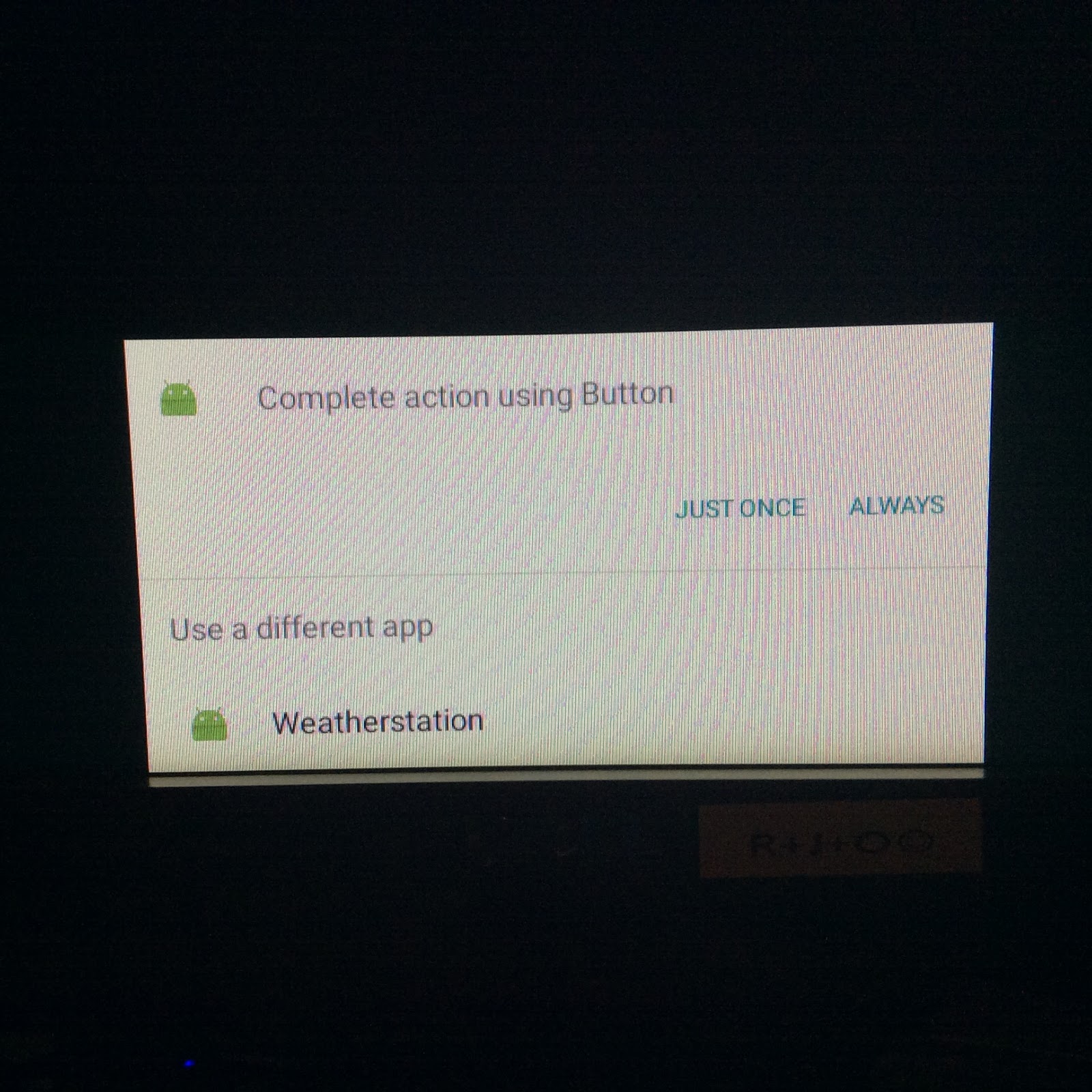
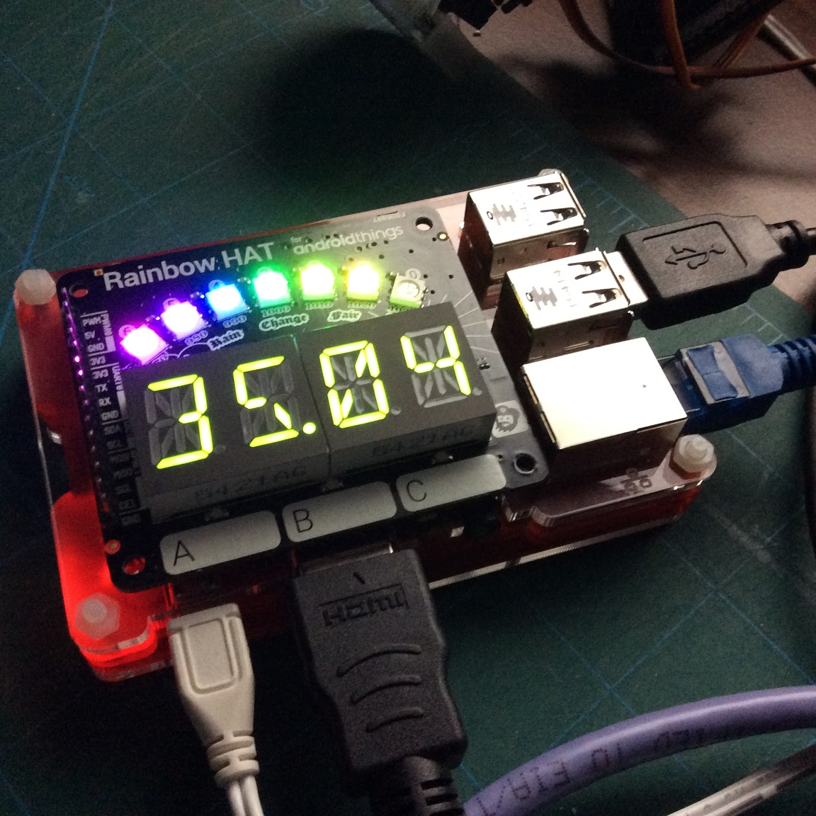
22. Now why not try the awesome weather station app which really lights up the Rainbow HAT. Follow steps 4-17 above but choose the weather station Github repo instead. Once you've deployed it, reboot the Pi. When it restarts you should be given the option as to which app you want to run. Connect a mouse to the Pi and choose the Weatherstation.
23. That's it! Now get stuck into some Java coding and explore some of the other sample code available.
After last week's Wimbledon Raspberry Jam, a few people asked me for instructions for getting Pimoroni Flotilla working in a completely offline environment. Obviously you need an Internet connection to do all the installing, but following these instructions should enable you to use Flotilla and all the great Cookbook stuff when you don't have Net access.
Here is a brief description of the steps I performed. This will almost certainly not work exactly the same way with future releases of the software and may not even be necessary!
1. Start with a fresh install of Raspbian and PIXEL. Do the usual update and upgrade:
4. Change into the flotilla-rockpool directory and switch to the Edge branch.
cd floilla-rockpool
git checkout edge
git fetch
5. Now for the tedious bit. All the hyperlinks in the examples in the Cookbook are pointing at online resources. We need to change them so that they point at our local cloned copy of Rockpool. Basically you need to go through each of the Cookbook recipe directories (in /home/pi/flotilla-cookbook) and edit the index.html file: change wherever it says 'http://flotil.la/rockpool/' to 'file:///home/pi/flotilla-rockpool/' (note the three /s after file). You could use a bash script to trawl through the whole directory or just open each one manually (Geany on the Pi is a good editor) and do a find/replace.
6. Finally, to make sure all the examples (especially Synth) work correctly with local files, you need to launch Chromium with some extra flags. I created a separate Desktop shortcut to make this simple. Create a file called flotilla-offline.desktop in /home/pi/Desktop
7. An icon should appear on the Desktop. Run it! I recommend adding Chromium bookmarks to each of the modified index.html files in each of the Cookbook recipe subdirectories. I also added a bookmark for the local version of Rockpool (file:///home/pi/flotilla-rockpool/index.html)
One of the first things I used a raspberry Pi for was to build a simple CCTV system. In fact that original model B is still up and running and today. It is a nice compact, self contained system.
However the addition of a camera capability to the Pi Zero opened up the possibilities for even smaller photography ideas.
Those rambunctious pirates at Pimoroni were quick off the mark with their dinky Little Bro kit. This is a smart CCTV sign that has a hole for the camera and comes with a mounting bracket for the Pi Zero which also allows you to fix the whole thing to a wall. When I wanted to make a timelapse of some garden work that was happening I simply used some string to hang the Little Bro from the window handle. This worked fine although it was a bit wobbly (especially when the window as opened) and when I had to adjust something I didn't manage to put it back up without altering the field of view slightly (you can see that the picture jumps slightly at about 00:10). It was also difficult to get the camera as close to the glass to keep reflections to a minimum.
Then The PiHut launched the excellent ZeroView, designed for exactly this sort of thing. It uses two sucker pads to stick to a window thus keep the camera as close to the glass as possible. Because the frame can be removed from the suckers while leaving them attached to the window, it also allows for easy adjustment and replacement without altering the field of view.
Initial tests confirmed that this was genius!
Remixing my original CCTV build (which uses Motion to detect movement and then uploads the resulting movie to Dropbox) was easy. On the first night of testing I managed to catch this wily fox sneaking through my garden at dawn.
However there were a couple of issues about making this a permanent installation that I wanted to address:
1) My experience of headless Pis and wifi is that sometimes the computer drops off the network. Although the power management for dongles seems to be much improved now, I wanted an easy way of seeing that the Zero was still connected.
2) Suckers are effective but not always reliable, especially in a window which might experience big changes in temperature.
So as a combined solution to both of these, I used a ProtoZero board, an accelerometer and an RGB LED.
Some simple python checks the accelerometer and looks for abrupt changes in the values reported, to detect if the Pi falls off the window. In this event it uploads a picture of Humpty Dumpty to DropBox. The same code also periodically checks that it is still connected to the Internet (by pinging Google) and changes the colour of the RGB LED from green to red. There are a few other visual cues too: the LED flashes blue when the baseline accelerometer readings are being measured at start-up and also flashes green when a ping test is underway. This is run at startup via /etc/rc.local.
#!/usr/bin/python3 from gpiozero import RGBLED from adxl345 import ADXL345 import time, numpy from datetime import datetime import dropbox import urllib3.contrib.pyopenssl urllib3.contrib.pyopenssl.inject_into_urllib3() import os,sys,logging
logfile = "/home/pi/cctv-"+str(datetime.now().strftime("%Y%m%d-%H%M"))+".csv" logging.basicConfig(filename=logfile, level=logging.DEBUG, format='%(asctime)s %(message)s', datefmt='%Y-%m-%d, %H:%M:%S,') led = RGBLED(26,13,6) eggfile='/home/pi/Humpty-Dumpty.gif' adxl345 = ADXL345() client = dropbox.client.DropboxClient('<ENTER YOUR DROPBOX KEY HERE>') #print('linked account: ', client.account_info()) logging.info('linked account: ', client.account_info()) axes = adxl345.getAxes(True) #print("ADXL345 on address 0x%x:" % (adxl345.address)) logging.info("ADXL345 on address 0x%x:" % (adxl345.address)) t = 0 x_av = 0 y_av = 0 x_values = [] y_values = [] #print('Calibrating....') logging.info('Calibrating....') led.blink(on_time=0.1,off_time=0.1,on_color=(0,0,1), n=50,background=True) while t < 100: axes = adxl345.getAxes(True) x = axes['x'] y = axes['y'] # print(x) x_values.append(x) y_values.append(y) time.sleep(0.1) t+=1 x_av = numpy.mean(x_values) y_av = numpy.mean(y_values) x_range = numpy.max(x_values) - numpy.min(x_values) y_range = numpy.max(y_values) - numpy.min(y_values) logging.info('Set mean x: ' + str(x_av)) logging.info('Set range x: ' + str(x_range)) logging.info('Set mean y: ' + str(y_av)) logging.info('Set range y: ' + str(y_range)) led.color = (0,0.2,0) counter = 0 jiggle = 5 while True: axes = adxl345.getAxes(True) x = axes['x'] y = axes['y'] if ((x > (x_av + (jiggle*x_range))) or (x < (x_av - (jiggle*x_range)))) and ((y > (y_av + (jiggle*y_range))) or (y < (y_av - (jiggle*y_range)))): #print('Humpty') logging.info('Humpty') led.color = (1,0,0) f = open(eggfile, 'rb') response = client.put_file(eggfile,f) f.close() time.sleep(1) time.sleep(0.1) counter +=1 if counter > 6000: #print('Checking network comms...') logging.info('Checking network comms...') counter = 0 response = os.system("ping -c 3 8.8.8.8") if response == 0: logging.info('I pinged Google successfully') led.blink(on_time=0.1, off_time=0.1, on_color=(0,0.5,0), n=3, background=False) led.color = (0,0.2,0) else: logging.info('Comms Down :-(') led.blink(on_time=0.1, off_time=0.1, on_color=(1,0,0), background=True)
Notes:
1) I used numpy to calculate the means and ranges which is really lazy - especially as numpy takes ages to compile on a Pi Zero.
2) I started from a fresh instal of jessie-lite. In addition to the Python libraries at the top of the code, you'll also need to install the following Raspbian packages:
It had been a long
journey from last year's Skycademy to get to this launch. Being situated just a few miles from
Heathrow was always going to mean that launching from school would be
tricky unless it involved everybody getting up a silly-o'clock
(before flights started) and chasing through rush hour.
So finding a launch
site close enough to be practical but far enough outside the LondonControl Zone (which defines the busy airspace around London) to gain
CAA approval took a several months and a few applications and phone
calls.
But now I had one I
thought was suitable;. Even then, our launch permission comes with
wind restrictions: the balloon must drift South or South West (i.e.
away from London). This isn't as bad as it sounds because,
realistically, you wouldn't want to chase a balloon heading in any
other direction.
Thursday's flight
was to be the first, long-awaited test from this site. Wind
conditions over Easter were rubbish and we'd already aborted a
planned launch on Tuesday because of bad weather (heavy ran and
wind). Although conditions had improved and it was a dry day, it
remained overcast and gusty (30mph) during the morning. Although
things looked like improving even further by the weekend, Nick
wouldn't be able to make it then so I decided to press ahead with the
launch. Despite the blowy ground winds, the balloon wasn't due to
travel too far and the predicted landing site was in the South Downs
National Park. Tweaking the launch parameters to avoid coming down
in Petersfield meant the burst altitude was lower than we'd like at
just(!) 27km, but as this was really a test of the launch site
conditions, we didn't mind too much.
We arrived at the
site at about 10:30 and set about finding a sheltered area. When I'd
reconnoitred a couple of days earlier I'd found a ridge that seemed
to provide a block for the wind. Although it was deficiently calmer
there, it was still pretty gusty and an ordinary balloon staked out
on the ground sheet was being constantly blown at about a 45 degree
angle. However the sun was started to break up the clouds and with a
long, clear area free from obstructions in the balloon's direction of
travel, we decided to go ahead, over-filling if necessary.
Apart from getting
slightly lost on the way back to the car to retrieve all the kit,
pre-flight prep went smoothly. We'd tested everything in the days
before the flight and our payload appeared on the HabHub map a minute
after we booted up the Raspberry Pi A+. We were lucky enough to have
two RTTY receivers (with an SDR dongle as back-up) and a LORA
receiver with us (plus another one connected to a roof aerial back at
my house) so we were fairly confident of our ability to track the
balloon.
We attached the
parachute to the payload and got ready to fill the balloon. As soon
as it began to inflate it was clear that adding enough helium for the
correct neck lift was going to be tricky to estimate: the balloon was
being buffeted by the wind and required all four of us to hold
steady. Rather than under-filling, (we think) we put in more helium
than required. Certainly the balloon was pulling away quite fiercely
by the end of the process.
Now to launch. The
chirping from the RTTY receiver told us that the radios were still
working and after a quick check to see that images were being
uploaded, we were ready to go.
Picture by @duck_star
Ozzy held the
balloon while Jasper had the parachute and I had the payload. The
balloon was released and Oz gently played out the line until it
reached the parachute. Jasper repeated the procedure until the cord
started to tug on the payload and then I let go. Smooth!
Everything soared up
into the sky, rapidly gaining height within a few seconds. By the
time we'd picked up cameras to take photos, it was nearly out of
site.
The Pi's eye view just after launching
A quick but thorough
pack-up and we headed back to the car park (managing to go the long
way round again). Mag-mount aerials deployed on the roof of the car
and we were off. The original predictions had the balloon coming down
just west of Petersfield, but the in-flight prediction was now
showing a touch-down nearer to Winchester so we headed there.
Pi's eye view 15 minutes into the flight
My roof-mounted
aerial back at home picked up the LORA transmissions from about 700m
altitude which was impressive and we soon saw several other RTTY
trackers uploading data to the website too.
By the time we
arrived in Winchester, the balloon seemed to have been caught in a
mini-tornado, spiralling round on itself over Liphook and never quite
managing to break free and head off towards us despite steadily
gaining altitude. Parking up on the roof of a multi-story car park we
had lunch and decided that the balloon was never going to make it
this far west before bursting: because we reckoned we'd added more
helium than required, we were expecting the burst to come earlier
than at the 27km we'd initially been aiming for.
As we headed back
East the balloon finally escaped its looping trajectory and started
heading west, gaining altitude even more rapidly. This also caused
the predicted landing area to shift towards Alresford, so we drove
there and found a nice pub with a beer garden to wait and see what
happened. By this point the altitude was approaching 26km so we were
expecting a burst at any time. But the altitude kept increasing until
we we approaching 30km. Surely it must burst now?
Pi's eye view from 34km up
We continued to
watch and fiddle with our receivers (Ozzy somehow managed to tune his
Yupiteru into a music station), chasers of all ages becoming
increasingly excited. The altitude continued to rise:
31km...32km...33km...34km… until at nearly 35K – and with much
shouting and excitement from the younger team members – the HabHub
icon changed from a balloon to a parachute and the altitude dropped
rapidly.
Although the landing
zone predictions were fluctuating, they seemed to be staying in
roughly the same area so we made for Cheriton. 3/4G connectivity was
quite patchy in this region so we kept loosing web access – and our
ability to upload telemetry from our receivers. Getting confused
(and slightly lost) we pulled up in a handy lay-by in a country lane
where we had a strong 4G signal. We looked at where we were and where
the payload was predicted to land and were pleased to discover that
the two locations were almost the same. Surrounded by open fields
this seemed like an perfect spot and we got out the binoculars and
stood around in the sunshine hoping that we'd actually be able to see
the payload drift in on its parachute.
It was not to be.
Suddenly at about
1km up, the predicted landing spot suddenly changed. Maybe the gusty
winds just blew it off course but the new touchdown spot was a couple
of miles away, right in the centre of (the excellently named) Itchen
Abbas. This was less than ideal. Plenty of trees, roofs, private
gardens and even a river to potentially foil our safe recovery plans.
We parked up at the
village hall and checked our data. Annoyingly, despite having has 5
bars of 4G in a remote field two miles away, here among the houses
and pubs of a fairly large village we had almost no signal on any
network. The good news was that we were still getting telemetry from
the payload and it appeared to stationary and on the ground. Typing
the latitude and longitude into Google Maps and managing to find a
scrap of 3G, we set off on foot.
Pi's eye view on the way down
After a few minutes
of heading in the wrong directions we got ourselves oriented and
started to close the gap between us and the payload. As we rounded a
corner and looked at the tablet I realised that the coordinates put
the landing site in the churchyard. We rushed in and there is was,
sitting peacefully amongst the weathered gravestones. It had landed
with the GPS facing upwards and with no signs of damage. There was
very little of the balloon left, suggesting that it had been a violent
burst when it eventually happened.
After some
respectful celebrations (we were in a churchyard after all) and the
obligatory recovery photos, we switched off the Pi and headed back to
the car for the journey home.
On reflection, the
flight was a great success. After the launch itself I was just happy
that we'd managed to sort out all the logistics and permissions, and
actually get a balloon off the ground. But having a successful chase
and recovery, coupled with the amazing altitude our payload achieved,
it was a really great day. All the tech worked and the only mishap
was me forgetting to turn off the valve on the helium canister before
removing the flexi-filler attachment thus wasting a load of gas.
We even got back
home in time for tea.
Take-aways from me:
The boys really
enjoyed the day. Some of the questions they asked demonstrated that
(a) they hadn't really been listening when I'd explained some aspects
of the flight and science as we prepared in the days prior to launch,
and (b) actually being involved in physical filling of the balloon,
the technical tracking and watching the live telemetry really
captivated them and got them thinking and asking questions in a way
that simply being told about stuff never will.
This is really a
team sport. Four people seemed the minimum needed to make things run
smoothly. Any less and we'd have had to make multiple trips from the
car to the launch site and would have really struggled with the
filling in the windy conditions. Multiple eyes on multiple screens
also made tracking and navigating easier.
Having a fixed
position LORA receiver with a reliable Internet connection is a good
idea. It means that you have telemetry being uploaded even when you
have no reception in the chase car, or are unable to upload yourself
due to no local 3G/4G.
Altitude telemetry from LORA
A checklist
including pictures of how to fill and tie off the balloon is really
useful. Diagrams and printouts of calculations save you having to
remember stuff when you're busy.
You can never have
too many receivers and Internet uplinks (preferably on different
networks) with you.
Picture by @duck_star
Don't rush into a
launch if conditions aren't suitable. But equally, don't be put off
if absolutely everything isn't ideal. It probably never will be, and
predictions will never be perfectly accurate either.
The NatureBytes Raspberry Pi camera kit is an excellent way to capture great photos of wildlife.
The lovely injection-moulded case is perfect for keeping everything nice and dry when deployed outside. the only problem I encountered was using the supplied Raspbian image: the GUI that ships is really nice and will be well suited to people using a Pi for the first time. But on a Raspberry Pi model A+ it can be quite resource intensive and I found myself getting frustrated with the performance.
Personally I wouldn't really consider using X-windows on an A+: it just doesn't have the muscle.
So I thought I'd put together a bare-bones installation that just runs the code necessary to detect motion with the PIR and take photos. I'm not bothered about saving onto a USB drive either: I'm happy to use the SD card and then connect the Pi to a network and extract using ssh.
So here is my recipe for building a quick, low profile image that works really well on an A+. Note that this does not include any windowing system so it's command line all the way!
5) Add the following code to a file (e.g. nblite.py). This makes use of the great gpiozero library to handle the PIR and starts a new logfile every time the code is run. Each image is date/timestamped and saved into /home/pi. The Pi will keep taking photos every half a second as long as motion continues to be detected.
The Adafruit Feather boards are a great size and the growing ecosystems of add-ons and compatible boards is really impressive.
This blog describes a quick-start project for the ESP8266 Huzzah Feather board with a Neopixel featherwing to provide a simple status indicator.
We're going to use the ESP8266 to scan for available WiFi networks and alert us if any insecure (open, with no encryption and requiring no password) networks are found. This might be a useful sensor for the corporate environment where sysadmins want to ensure nobody is introducing un-protected access routes into their network. Red LEDs indicate that a possible rogue AP has been found, all green means everything is ok.
Hardware Setup
Depending on where you purchased you boards from, you may need to solder header pins. I added female headers to the Huzzah and males to the NeoPixel FeatherWing so that the two simply connect together like a couple of mating beetles!
The Neopixel_FeatherWing needs to have a jumper set to work with the EXP8266 Huzzah Feather. Using a sharp knife, break the preset jumper on pin 16 and then solder across the jumper on pin 15.
Software Setup
1. Ensure your Arduino Sketch editor is the latest version
3. Download the Adafruit Neopixel library for Arduino. Download the zip file from the Github page and unzip it. Then rename the extracted folder to Adafruit_Neopixel and copy it to your Arduino libraries folder (on a Mac that's in /home/<user>/Documents/Arduino/libraries).
4. Add the ESP8266 board package as an additional board into the editor's preferences.
5. Now go to Tools -> Board: -> Boards Manager
Scroll down to the bottom and click the ESP8266 entry, then click the Install button
6. Once that's finished, go back to Tools-> and select the Adafruit Huzzah ESP8266 board. All the default values should be set, but make sure the Port setting corresponds to how you have connected your Feather (on a Mac it is normally /dev/cu.SLAB_USBtoUART).
7. Now for some test code. Copy this into your Ardunio Sketch editor and then click the Upload button.
#include "ESP8266WiFi.h" #include <Adafruit_NeoPixel.h> #ifdef __AVR__ #include <avr/power.h> #endif Adafruit_NeoPixel pixels = Adafruit_NeoPixel(32, 15, NEO_GRB + NEO_KHZ800); int OPEN = 0; void allOn(char* col); void setup() { pixels.begin(); Serial.begin(115200); // Set WiFi to station mode and disconnect from an AP if it was previously connected WiFi.mode(WIFI_STA); WiFi.disconnect(); delay(100); Serial.println("Setup done"); } void allOn(char* col) { //Pulsing if (col == "red"){ // pixels.Color takes RGB values, from 0,0,0 up to 255,255,255 for (int p=0;p<200;p++){ for(int i=0;i<32;i++){ // pixels.Color takes RGB values, from 0,0,0 up to 255,255,255 pixels.setPixelColor(i, pixels.Color(p,0,0)); // Moderately bright red color. pixels.show(); } delay(1); } for (int p=200;p>0;p--){ for(int i=0;i<32;i++){
// pixels.Color takes RGB values, from 0,0,0 up to 255,255,255 pixels.setPixelColor(i, pixels.Color(p,0,0)); // Moderately bright red color. pixels.show(); } delay(1); } } else { for (int p=0;p<200;p++){ for(int i=0;i<32;i++){ // pixels.Color takes RGB values, from 0,0,0 up to 255,255,255 pixels.setPixelColor(i, pixels.Color(0,p,0)); // Moderately bright green color. pixels.show(); } delay(1); } for (int p=200;p>0;p--){ for(int i=0;i<32;i++){ // pixels.Color takes RGB values, from 0,0,0 up to 255,255,255 pixels.setPixelColor(i, pixels.Color(0,p,0)); // Moderately bright green color. pixels.show(); } delay(1); } } //} } void loop() { Serial.println("Starting Scan"); // WiFi.scanNetworks will return the number of networks found int n = WiFi.scanNetworks(); Serial.println("Scan complete"); if (n == 0) Serial.println("No networks found"); else { Serial.print(n); Serial.println(" networks found:"); for (int i = 0; i < n; ++i) { // Print SSID and RSSI for each network found Serial.print(i + 1); Serial.print(": "); Serial.print(WiFi.SSID(i)); Serial.print(" ("); Serial.print(WiFi.RSSI(i)); Serial.print(")");
byte enc = WiFi.encryptionType(i); Serial.print(" Encryption: "); Serial.println(enc,HEX); // No encryption - open network if (enc == 7){ OPEN++; }